A compact control board may hold dozens of components, tiny solder joints, and firmware-critical connections. One weak joint can stop an otherwise polished product. That is why pca assembly deserves attention early, not only after a prototype fails. It turns a bare printed circuit board into a working assembly through component placement, soldering, inspection, and testing. The process looks straightforward. The details are not.
Demand makes those details more important. The World Semiconductor Trade Statistics (WSTS) Fall 2024 forecast projected global semiconductor sales of $627.6 billion in 2024 and $697.2 billion in 2025. These figures reflect a large, growing electronics ecosystem, though they do not guarantee demand for any single product. For manufacturers, they underline the need to plan component sourcing, production capacity, and quality checks together. IPC standards, including IPC-A-610 for electronic assembly acceptability, offer a shared framework for evaluating workmanship. Yet a standard cannot replace clear design files, suitable process controls, or honest communication between a product team and its assembly partner. A small footprint error can still cause rework. That part is easy to underestimate.
Choosing an assembly partner is therefore a practical decision about risk, not just unit price. A capable provider can help match production methods to board complexity, volume, and inspection needs. The right choice may shorten a launch; the wrong one can add delays and scrap. There is no magic shortcut. This guide examines the factors that make pca assembly a strong fit, where its limits appear, and what questions to ask before committing a design.
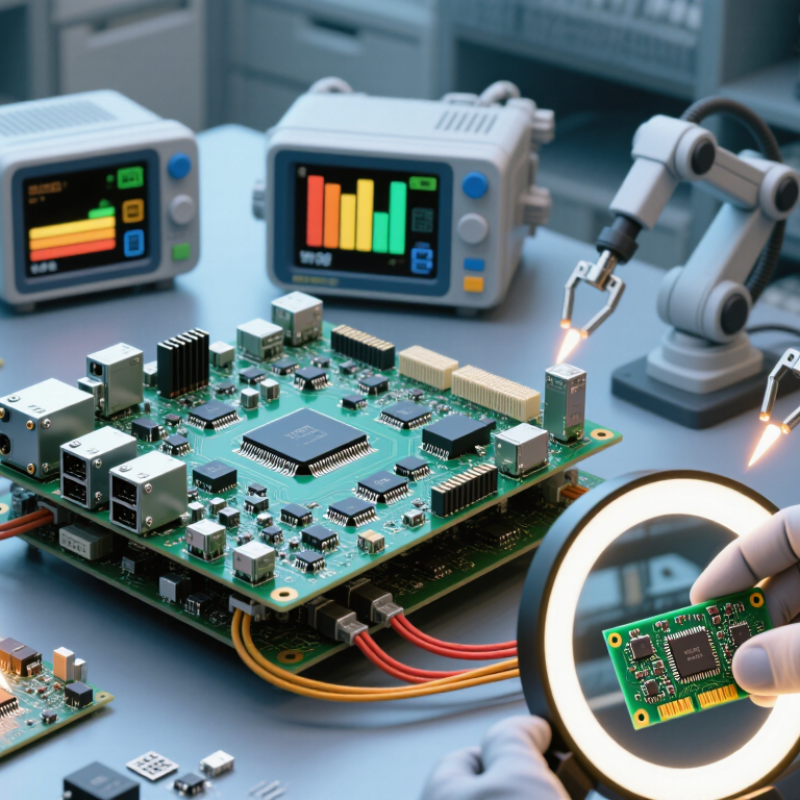
In electronics manufacturing, PCA assembly means fitting electronic components onto a printed circuit board and joining them electrically. The bare board provides copper pathways; the assembled board becomes a working circuit. That distinction matters. A board can look complete yet fail if a component is reversed, a solder joint is weak, or a connector sits slightly out of position.
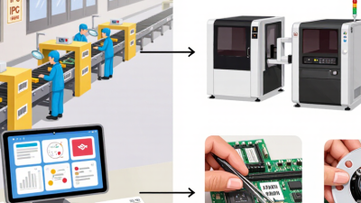
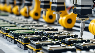
Assembly typically starts with solder paste applied through a stencil. Automated equipment places small components, while larger parts may need manual handling. The board then passes through a reflow oven, where heat melts the solder and secures the parts. For example, a tiny resistor beside a processor may be only a few millimeters long, so placement accuracy is essential. Small details count.
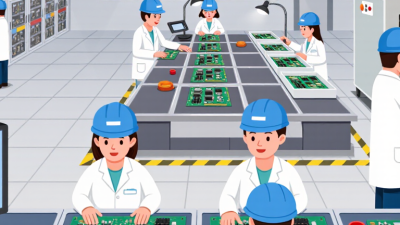
Inspection may include cameras, electrical tests, and checks of solder joints. These steps help catch issues such as missing parts or unintended connections before products reach final assembly. Test coverage depends on the design, though, and no single inspection catches everything. It is easy to assume automation guarantees quality; it does not. Clear design files, suitable component choices, and careful process controls all matter. Some projects also need design changes after early production, which can be frustrating, but those findings can improve reliability.
| Dimension | What It Means | Typical Assembly Activity | Why It Matters |
|---|---|---|---|
| PCA definition | PCA means printed circuit assembly: a bare printed circuit board populated with electronic components and joined electrically. | Components are mounted and soldered to the board according to the design and assembly documentation. | It distinguishes an assembled board from a bare PCB, which has conductive patterns but no mounted components. |
| Surface-mount technology (SMT) | Components are placed on conductive pads on the board surface. | Solder paste is applied through a stencil, components are placed, and the board is commonly heated in a reflow oven. | SMT supports compact layouts and automated placement, making it suitable for many modern electronic products. |
| Through-hole assembly | Component leads pass through holes in the board and are soldered to conductive pads. | Parts may be inserted by hand or equipment and soldered using wave soldering or selective soldering. | It can provide strong mechanical attachment and is often used for connectors or components that require it. |
| Mixed-technology assembly | A board uses both surface-mount and through-hole components. | The assembly sequence is planned around component types, soldering methods, and any required protection of previously assembled parts. | It allows a design to combine compact SMT parts with components better suited to through-hole mounting. |
| Inspection and testing | Checks are used to assess assembly quality and, where specified, electrical operation. | Methods may include visual inspection, automated optical inspection, in-circuit testing, or functional testing. | The appropriate checks depend on the product design, test access, production requirements, and acceptance criteria. |
| Assembly inputs | Production depends on clear design and component information. | Common inputs include PCB fabrication data, a bill of materials, component placement data, and assembly notes. | Complete, consistent documentation helps reduce interpretation errors and supports accurate component placement. |
| Potential benefits | Assembly combines the board and components into a populated electronic subassembly. | Production methods can be selected to suit the design, component package types, and planned volume. | A completed PCA can be integrated into a larger product or enclosure and used as part of its electronic system. |
| Design considerations | The board layout and component choices affect manufacturability and testability. | Design reviews can consider component spacing, footprints, soldering access, thermal requirements, and test points. | Addressing these factors early can make assembly and inspection more straightforward. |