
What Is a Variable Frequency Converter?

A Variable Frequency Converter changes the frequency and voltage supplied to an alternating-current motor. This lets operators adjust motor speed to suit the task. At a pump, that can mean matching water flow without running the motor at full speed constantly. Small adjustments matter. A converter typically uses a rectifier, a DC link, and an inverter to reshape incoming power. The exact design varies, so the label alone does not tell you how a unit will perform.

Austin Hughes, author of Electric Motors and Drives, has written extensively about electric-drive principles. A careful paraphrase of that practical idea is: “Motor speed control begins by controlling the electrical supply.” This is a paraphrase, not a verbatim quotation. It points to the converter’s purpose, but not every detail. Motor type, load, wiring, cooling, and setup all affect real-world results.

A useful introduction should explain how conversion works, where these devices are used, and what buyers should check before installation. It should also distinguish a converter from related motor-control equipment, since terminology can vary between manufacturers. A compact unit beside a workshop fan may look simple. Its settings still deserve care. I would not treat adjustable speed as an automatic energy saving: benefits depend on the application and operating conditions. The sections ahead unpack the principle, key components, common uses, and practical limits without treating one configuration as right for every motor.
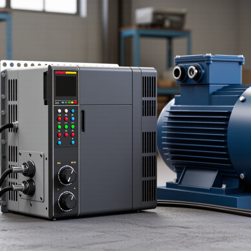
What Is a Variable Frequency Converter?

Definition and Purpose of a Variable Frequency Converter

A variable frequency converter is an electronic device that changes the frequency of power supplied to an alternating-current motor. Many systems also adjust voltage to suit the selected frequency. By controlling these electrical inputs, the converter can regulate motor speed rather than relying on fixed-speed operation. In practice, an operator might slow a pump when demand falls or adjust a fan to maintain steady airflow. Small changes can matter.

The purpose is not only speed control. A converter can provide a gradual motor start, reducing sudden mechanical strain on belts, couplings, and pipes. It can also help match energy use to actual process needs, especially in pumps and fans that often run below full capacity. Results depend on the application. A poorly selected unit may cause excess heat, electrical noise, or unstable operation. Motor cooling can also become a concern at low speeds, since the shaft-mounted fan turns more slowly. Check the motor’s ratings, load requirements, and operating range before choosing equipment. Installation details matter, too. A converter is not a universal fix.


How a Variable Frequency Converter Controls Motor Speed

What Is a Variable Frequency Converter?

How a Variable Frequency Converter Controls Motor Speed

A variable frequency converter changes the frequency and voltage supplied to an AC motor. It typically converts incoming AC power to DC, then synthesizes output at a controlled frequency. Because motor speed closely follows supply frequency, lowering the frequency slows the motor; raising it speeds the motor up. The converter can also ramp changes gradually, helping reduce jolts in a conveyor or pump system. Small detail, big effect.

The International Energy Agency’s 2011 report, Energy-Efficiency Policy Opportunities for Electric Motor-Driven Systems, estimated that motor-driven systems use 43–46% of global electricity. In centrifugal pump applications, the U.S. Department of Energy’s pumping-system sourcebook explains the affinity laws: power can vary roughly with the cube of rotational speed. In an idealized case, a 10% speed reduction could cut pump power by about 27%. Real systems differ. Static head, drive losses, and operating conditions can shrink the savings, so measured results matter more than a rule of thumb.

Tips: Check the motor nameplate and load profile before selecting a converter. Record speed, pressure, and power at normal operating points. A lower setting is not automatically better; verify that the process still meets its needs.

Key Components of a Variable Frequency Converter

A variable frequency converter changes the frequency and voltage supplied to an AC motor, allowing its speed to be adjusted. Its main components work together to convert incoming power, shape the output, and respond to operating conditions. The exact layout varies by design.

The rectifier converts incoming AC power into DC. A DC bus, often containing capacitors and sometimes inductors, smooths and stores energy between conversion stages. The inverter then switches this DC into variable-frequency AC for the motor. Control electronics set the output frequency and voltage, while sensors can monitor current, temperature, or motor speed. Protective circuits help respond to faults such as overloads or excessive heat. That matters. In practice, the neat block diagram can be misleading: wiring, cooling, and motor load all affect performance.

Tips: Check that the converter’s current rating suits the motor, not just its power rating. Keep cooling paths clear, and follow the manufacturer’s wiring and commissioning instructions. Heat is real. A display reading alone may not reveal every installation issue.

What Is a Variable Frequency Converter? - Key Components of a Variable Frequency Converter

Component Main Function Typical Design Details Why It Matters
Rectifier Converts incoming AC power into DC power. Common designs use a diode bridge; some converters use controlled switches or active front ends. Its design affects input current, harmonic distortion, and whether power can be returned to the supply.
DC Link Stores and smooths DC power between the rectifier and inverter. Usually includes electrolytic or film capacitors; some designs also include a DC choke. A stable DC bus helps the inverter produce a controlled motor output and absorb short-term power fluctuations.
Inverter Bridge Switches DC power to create variable-frequency, variable-voltage AC output. Typically uses six power semiconductor switches, such as IGBTs, in a three-phase bridge. Output frequency controls motor speed; output voltage is adjusted to suit the operating condition.
Gate Driver Provides the switching signals and drive power required by the inverter devices. Often includes electrical isolation, under-voltage monitoring, and protection against excessive switching current. Accurate, protected switching supports reliable operation and helps prevent power-device damage.
Control Board Processes commands and calculates switching patterns for the motor output. May support scalar (V/f) control or more advanced vector-control methods, depending on the application. It sets operating behavior such as acceleration, deceleration, speed reference, and fault response.
Sensors and Protection Circuits Monitor electrical and thermal conditions and trigger protective actions. Common measurements include current, DC-bus voltage, and heatsink temperature. Protection functions can respond to conditions such as overcurrent, overvoltage, overheating, or phase loss.
Cooling System Removes heat generated by power electronics and other internal components. May use a heatsink with natural convection or forced-air fans; larger equipment may use liquid cooling. Adequate cooling helps keep components within their rated operating temperatures.
Input and Output Terminals Provide connections for the AC supply, motor, grounding, and control wiring. Power terminals are sized for the converter’s rated current; control terminals handle low-voltage signals. Correct wiring, grounding, and cable selection are essential for safe installation and electromagnetic compatibility.

A variable frequency converter (VFC), also commonly called a variable frequency drive, controls an AC motor by adjusting the frequency and voltage of its electrical supply. Component selection and configuration vary with the converter’s rating and application.

Common Types of Variable Frequency Converters

Common Types of Variable Frequency Converters

Most modern variable frequency converters use an AC-DC-AC design. They first convert incoming alternating current into direct current, then create output at a controlled frequency. A DC bus, often containing capacitors, smooths the power between these stages. This type is common in pumps, fans, and conveyor systems. It can adjust motor speed without mechanical changes.

Voltage-source inverters are widely used in these converters. They hold a relatively steady DC voltage and switch it to produce variable-frequency AC. Many use pulse-width modulation to shape the output and control motor speed. Current-source inverters regulate output current instead, and may suit certain high-power applications. They usually need different components and protection. That matters.

Direct AC-AC converters, including cycloconverters, change input frequency without a conventional DC bus. They are often considered for large, slower motors, such as those used in heavy industrial equipment. Control methods also vary: basic V/f control is practical for steady loads, while vector control can provide more precise torque at low speeds. The categories overlap a little, which can confuse buyers. Not always. Check the motor’s voltage, load, and operating range before choosing a converter; real installations may behave differently from a simple specification sheet.

What Is a Variable Frequency Converter? — Common Types

An idealized three-phase output waveform at three fundamental frequencies. Variable frequency converters commonly use voltage-source or current-source inverter topologies; scalar V/f and vector control are common control methods. Actual output waveforms are typically pulse-width modulated.

The plotted values are normalized mathematical sine waves, not measured equipment data. Changing the output frequency changes the waveform’s number of cycles over the same time interval, allowing a motor’s speed to be controlled.

Industrial Applications and Selection Factors

What Is a Variable Frequency Converter?

Industrial Applications and Selection Factors

A variable frequency converter changes the frequency and voltage supplied to an AC motor, allowing operators to adjust motor speed. In a water plant, it can slow a pump when demand drops. On a packaging line, it can help a conveyor start smoothly instead of jolting its load. These adjustments can improve process control and reduce energy use, especially with variable-torque loads such as fans and pumps. Savings are not automatic; they depend on the application and operating hours.

Selection starts with the motor nameplate. Check voltage, full-load current, power, and required speed range. Then assess the load: a loaded conveyor may need stronger starting torque than a ventilation fan. Consider duty cycle, overload duration, braking needs, and the installation environment. Dust, heat, and moisture matter. A converter rated for a clean control room may not suit a hot, dusty production floor without suitable protection and cooling.

Compatibility deserves a closer look. Long motor cables, sensitive instruments, and nearby equipment can affect electrical noise and insulation stress. Check whether filters, shielded cables, or reactor components are needed. Confirm control interfaces and safety functions with the existing system. A calculation on paper is only a starting point; commissioning measurements may expose assumptions that need revisiting. The smallest suitable unit is not always the best fit. A little margin can help, but excessive oversizing may complicate protection settings and cost more.