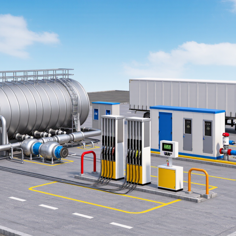
An LNG refueling station is more than a dispenser beside a storage tank. It is a connected system designed to receive, store, transfer, and measure liquefied natural gas under controlled conditions. A typical LNG Refueling Station Product range may include cryogenic storage tanks, transfer pumps, dispensers, flow meters, vapor-handling equipment, valves, and monitoring controls. Each component has a specific job. A pump moves cold fuel through insulated piping. A dispenser connects to the vehicle and records the delivered quantity. Temperature and pressure readings help operators track changing conditions.
The best products depend on how a station will be used. Expected vehicle traffic, refueling speed, site layout, and available maintenance support all matter. So does the equipment’s compatibility with the intended vehicles and the station’s operating conditions. Small details count: insulation quality, clear display readings, accessible shutoff controls, and straightforward service procedures can affect everyday operation. Not glamorous, but important. Product specifications and supplier documentation should be reviewed carefully, and qualified professionals should assess the complete system before installation. A product list can make selection look simple. It often isn’t. This guide examines the main LNG station equipment categories and the practical questions buyers can ask when comparing them, without treating any single product as the right choice for every site.
LNG storage tanks are the central equipment in a refueling station. They hold liquefied natural gas at cryogenic temperatures, near -162°C, until a vehicle is ready to refuel. A typical system uses an inner vessel suited to extreme cold and an outer shell that protects the insulation. Some designs use vacuum insulation; others use layered materials such as perlite. The right choice depends on capacity, site conditions, delivery schedules, and operating pressure. Cold is unforgiving.
Containment involves more than the tank walls. Pressure, temperature, and liquid-level instruments help operators monitor changing conditions. Pressure-building equipment can support delivery when tank pressure is low, while relief devices provide protection against excess pressure. Piping, valves, and connections also need cryogenic-rated materials and careful installation. A small leak at a connection can create a serious cold hazard, so routine checks should include fittings, supports, and visible signs of abnormal frosting.
Selection deserves a practical review. A tank that fits the available space may still be poorly matched to peak demand or truck delivery intervals. Insulation performance, maintenance access, foundation design, and monitoring arrangements all matter. Specifications can look complete on paper, yet overlook how staff will inspect hard-to-reach components. That is worth questioning. Clear operating procedures and qualified inspections help turn a well-designed containment system into dependable station equipment.

An LNG refueling station depends on three linked systems: cryogenic pumps, vaporizers, and pressure-control equipment. The U.S. Department of Energy’s Alternative Fuels Data Center notes that liquefaction reduces natural gas volume by roughly 600 times. Compact storage makes transfer efficient, but it demands equipment built for extreme cold. Pumps move LNG from storage tanks to dispensers while limiting heat gain and unwanted vapor formation. Look for stable flow, compatible seals, and clear maintenance access—not just rated capacity. Small parts matter. A worn seal can interrupt an otherwise capable station.
Vaporizers convert liquid fuel into gas where a station design requires gaseous delivery or pressure conditioning. Ambient-air units avoid direct combustion, yet icing can reduce output in cold, damp weather. Heated systems can provide steadier vaporization, but add controls and maintenance. Pressure regulators, sensors, and relief devices help keep delivery within the dispenser’s specified operating range. GIIGNL reported 401.4 million tonnes of global LNG trade in 2023 in its 2024 Annual Report. That scale makes dependable station hardware more than a procurement detail. No component is maintenance-free. Compare turndown, response time, inspection intervals, and parts access against actual duty cycles. Real weather and fueling peaks rarely match neat design assumptions.
An LNG refueling station depends on more than a storage tank. The dispenser controls and records fuel delivery, while its display helps operators check the transaction. Clear controls and visible status indicators matter, especially in cold or windy conditions. A screen that is hard to read can slow a busy fueling stop.
The nozzle and vehicle connection need careful compatibility. LNG is stored at very low temperatures, so these components must be designed for cryogenic service and form a secure connection. Insulated handles, robust seals, and a reliable locking mechanism help reduce exposure to cold surfaces and limit leaks. Small details matter. A worn seal may be easy to miss, so routine inspection should include seals, hose condition, and signs of icing. No single component makes a station safe; equipment condition and trained procedures work together.
Tips: Before fueling, check that the nozzle and vehicle connection are clean and undamaged. Follow the station’s operating procedure, and stop if a connection appears loose or abnormal. Keep the area around the dispenser clear. It is tempting to treat small icing as harmless, but that assumption deserves a second look.
Approximate LNG temperature at liquid-contact points during fueling
LNG’s normal boiling point is approximately −162°C at atmospheric pressure. Dispensers, nozzles, and vehicle-fueling connections that contact LNG are designed for cryogenic service; actual operating temperatures vary with pressure and fuel composition.
At an LNG refueling station, safety depends on systems that detect trouble early and respond predictably. Gas detectors monitor areas around dispensers, pipe connections, and storage equipment. Their placement matters: a sensor hidden behind a cabinet may miss a leak’s path. Temperature and pressure instruments also help operators spot abnormal conditions before equipment is stressed.
Monitoring panels bring these signals together and show alarms where staff can act on them. Clear labels and simple displays matter during a noisy shift. Emergency shutdown systems can stop fuel transfer and isolate equipment when defined hazards occur. Shutdown valves should be accessible, tested, and checked for reliable operation. Keep the response practical.
Routine inspection is not glamorous, but it catches loose connections, blocked vents, and sensors needing calibration. Records help teams notice repeated faults instead of treating each alarm as new. No system is perfect. A poorly understood alarm can be almost as troublesome as a missed one, so operators need hands-on training and clear response steps. Test procedures should reflect the station’s equipment and operating risks, with qualified personnel verifying that alarms and shutdown actions work as intended.
| Product or system | Primary function | Typical monitoring or control | Safety contribution |
|---|---|---|---|
| Cryogenic LNG storage tank | Stores LNG at cryogenic temperature before dispensing. | Liquid level, pressure, temperature, and tank status. | Insulation, pressure protection, and level alarms help manage cryogenic inventory and operating conditions. |
| LNG transfer and dispensing pump | Moves LNG from storage through the station's dispensing equipment. | Pump status, pressure, temperature, and flow, as provided by the station design. | Interlocks and shutdown controls can stop transfer when an abnormal condition is detected. |
| LNG dispenser and fueling connection | Delivers LNG to a vehicle through compatible fueling hardware. | Dispensed quantity and, depending on configuration, operating pressure and equipment status. | Compatible couplings and operating procedures help limit leakage and unintended release during fueling. |
| Emergency shutdown (ESD) system | Initiates a defined safe response when an emergency or specified fault occurs. | ESD pushbuttons, trip signals, valve position, and system status. | Can isolate LNG transfer by closing designated shutdown valves and stopping associated equipment, according to the engineered shutdown logic. |
| Emergency shutdown valves | Isolate selected sections of LNG piping when actuated. | Open/closed position and actuation status. | Provide a means to limit continued flow during an emergency; valve location and fail-safe action are determined by the design. |
| Natural gas detection system | Detects methane or combustible gas in designated areas. | Gas concentration and detector fault/status signals. | Alarms can alert personnel and may initiate ventilation or shutdown actions where included in the safety design. |
| Fire and cryogenic leak detection | Identifies fire conditions or signs of an LNG release in protected areas. | Detector alarms, device health, and system status. | Provides early warning and can be connected to site alarms or ESD logic as specified by the design. |
| Pressure and temperature instruments | Measure operating conditions in tanks and process piping. | Pressure and temperature readings, alarms, and instrument status. | Help operators identify conditions outside approved operating limits and support protective actions. |
| Safety instrumented system (SIS) or safety controller | Processes designated safety inputs and executes specified protective functions. | Safety inputs, logic status, output status, and detected faults. | Supports independently engineered safety functions where required by the hazard assessment and applicable standards. |
| Vent and pressure-relief equipment | Manages intended venting and protects equipment against excess pressure, as designed. | Relief-device condition and related pressure indications, where instrumented. | Provides engineered pressure protection and directs vented gas to designated locations where required by the system design. |
| Control and alarm system | Displays operating information and supports normal station control. | Process readings, equipment status, alarms, and event history, depending on configuration. | Helps operators recognize abnormal conditions and coordinate response; it does not replace independent protective systems where those are required. |
Note: Equipment selection, alarm settings, shutdown logic, and applicable codes depend on the station design, hazard assessment, local regulations, and authority requirements. LNG fueling station design may reference standards such as ISO 16924 and applicable national or local codes.
A reliable LNG refueling station depends on coordinated controls, accurate measurement, and equipment designed for cryogenic service. Automation systems monitor tank levels, line pressure, temperatures, and pump status from a central operator interface. Clear alarms help staff spot abnormal readings before they become operational problems. Simple matters, but they count.
Metering equipment tracks the amount of LNG dispensed and supports consistent transaction records. Depending on the station design, cryogenic-rated flow meters may measure mass flow directly. Pressure and temperature sensors provide useful context for interpreting readings. Calibration and routine checks matter; even a well-specified meter can drift or report poorly when installation details are overlooked.
Supporting components keep the system connected and controlled. Vacuum-insulated piping helps limit heat transfer, while suitable valves manage flow and isolate sections during maintenance. Pumps move LNG through the dispensing system, and emergency shutdown controls help stop operations when required. Gas detectors and carefully placed sensors add another layer of awareness. No layout is perfect: sensor placement, operator training, and maintenance access deserve review during design, not only after installation. A practical station brings these products together around clear procedures and dependable monitoring.
Precision Cable Assemblies
16830 Pheasant Drive
Brookfield, WI 53005
Phone: 262-784-7887
Fax: 262-784-0681