How to Choose a Three Phase Transformer?
Choosing a Three Phase Transformer begins with the actual electrical load, not a catalog page. A workshop with several motors may draw a different load at startup than during steady operation. The transformer must match the system’s primary and secondary voltages, frequency, and required kVA capacity. Small details matter. An incorrect voltage or insufficient capacity can cause poor performance, overheating, or unexpected interruptions.
Transformer author John J. Winders Jr. provides a useful engineering perspective in his work, Power Transformers: Principles and Applications. A concise paraphrase of that practical approach is: “Choose for the real duty, not the label alone.” This is a paraphrase, not a verbatim quotation. It points to factors that a simple rating may not show, including load cycles, motor starting, harmonics, ambient temperature, and installation conditions. Heat matters. So do cooling method, enclosure, impedance, and available space. A unit installed near dust, moisture, or limited ventilation may need different protection than one in a clean electrical room.
This guide explains how to compare transformer ratings, winding connections, insulation, and protection features. It also highlights questions to ask suppliers and qualified electrical professionals before purchase. Local technical requirements and applicable standards should be checked for the installation. A checklist helps, but it cannot replace a site-specific load assessment. That limitation is easy to overlook. The best choice is the one suited to the real operating conditions, with its assumptions clearly reviewed.
Understanding Three-Phase Transformers and Their Applications
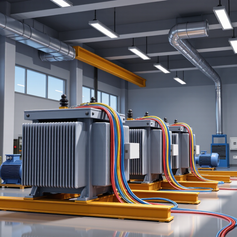
A three-phase transformer transfers power between three-phase circuits while changing voltage levels. It uses three coordinated magnetic paths, or a shared core arrangement, to serve the phases together. In practice, this supports reliable power for motors, pumps, commercial buildings, and industrial equipment. Not magic. Performance depends on load balance, operating conditions, and correct connections.
Primary and secondary windings can be connected in delta or wye. A wye secondary can provide a neutral for line-to-neutral loads, while delta connections suit other system needs. These choices affect voltage, grounding, and fault behavior, so they must fit the site design. For example, a workshop with large motors and lighting may need both suitable line voltage and a neutral. Check the nameplate, load schedule, and expected motor starting current. A quick voltage match is not enough.
When selecting a transformer, compare its kVA capacity with actual demand and likely growth, rather than simply choosing the largest unit. Consider insulation class, cooling method, indoor or outdoor placement, ambient temperature, and enclosure rating. Equipment such as variable-speed drives can create harmonics and extra heat, so review the load profile with a qualified electrical engineer. Measurements on site matter. A plan can look tidy on paper, yet cable lengths and ventilation may change the choice. That detail deserves a second look.
Determining Voltage, Power, and Load Requirements
Before choosing a three-phase transformer, list every supply and load voltage, including any secondary voltage needed by controls or equipment. A mismatch can leave a machine unusable, even when the kVA rating looks adequate. For a balanced load, estimate apparent power with kVA = √3 × volts × amps ÷ 1,000. At 400 volts and 80 amps, that is about 55 kVA. At a 0.9 power factor, the same load uses roughly 50 kW. These are working estimates, not a substitute for measured demand. The U.S. Department of Energy’s 2013 Distribution Transformers Technical Support Document estimated annual U.S. transformer losses at about 61 billion kWh, underscoring why efficiency and loading deserve attention.
Use the highest credible simultaneous demand, not the sum of every nameplate rating. Check motor starting current, variable-speed drives, nonlinear loads, ambient temperature, and expected expansion. A transformer serving several motors may need capacity for brief starting surges, while harmonics can add heating. Leave room. But avoid oversizing by habit: a lightly loaded unit can have unnecessary fixed losses. Compare the expected load profile with manufacturer loss data and applicable IEEE C57 guidance, then confirm primary taps, frequency, impedance, and protection with a qualified electrical designer. One thing is easy to miss: actual demand may differ from the spreadsheet. Record field measurements when available, and revisit the estimate if operating patterns change.
Selecting a Winding Configuration and Transformer Type
Choose the winding connection from the loads, grounding plan, and expected imbalance—not from voltage alone. Delta-wye designs are common where a grounded neutral must supply both three-phase motors and line-to-neutral loads. The delta winding can provide a path for certain triplen harmonic currents, but circulating currents may add heat. Neutral access matters. For mostly balanced motor loads, delta-delta may be suitable; it does not provide a neutral without additional equipment. Wye-wye can work well, though unbalanced loads and grounding details need careful review. That can be awkward in retrofit projects, where the existing neutral arrangement is not always documented.
Transformer type matters just as much. Dry-type units are often selected indoors where liquid containment is undesirable; liquid-filled units can suit outdoor installations and higher capacities, subject to site conditions. Core-type and shell-type describe magnetic construction, not the cooling medium. Check insulation class, enclosure, cooling, harmonics, fault levels, and available maintenance access against the actual duty cycle. The U.S. Energy Information Administration reports that roughly 5% of electricity is lost across transmission and distribution systems; this is not a transformer-only figure, but it underlines the value of reviewing loading and efficiency. A little caution helps. A nameplate choice can still miss real operating conditions. Include measured load data, future expansion, and the consequences of losing one phase before finalizing the specification.
Evaluating Efficiency, Cooling, and Installation Conditions
When choosing a three-phase transformer, compare efficiency at your actual load, not only at full rating. DOE’s 2016 distribution-transformer technical analysis separates no-load losses from load losses; both affect operating cost. No-load losses continue while the unit is energized, while winding losses rise with load. A lightly loaded transformer may therefore favor low core losses. Ask suppliers for guaranteed loss figures and use your hourly load profile to estimate annual energy use. A tidy spreadsheet can still miss future expansion.
Cooling and installation conditions matter just as much. IEEE C57.91-2011 states that, for thermally upgraded paper insulation, a winding hot-spot temperature around 110°C is the reference for normal aging; roughly 6°C higher can double the aging rate. That is a real cost. Check ambient temperature, altitude, enclosure ventilation, dust, moisture, and indoor clearance before selecting natural or forced cooling. Confirm the floor can carry the filled unit’s weight, and leave room for cable bends, inspection, and airflow. A cramped room can undermine a sound design.
Tips: Match the nameplate rating to measured peak demand, then add a realistic growth margin. Verify site conditions on a walk-through; drawings can be optimistic. Compare loss guarantees, cooling requirements, and maintenance access together—not as separate checkboxes.
Checking Standards, Protection, and Maintenance Requirements
A three-phase transformer should meet the standards required at its installation site, not just a specification sheet. Check the applicable IEC or IEEE requirements, local electrical rules, voltage tolerance, insulation class, and temperature-rise limits. Confirm that the rating covers both normal demand and realistic peak loads. A motor starting at dawn can change the picture.
Protection needs to match the transformer and the system around it. Review overcurrent settings, short-circuit withstand capability, grounding, and coordination with upstream and downstream devices. For liquid-filled units, assess suitable temperature and pressure protection; dry-type designs need appropriate ventilation and thermal monitoring. Keep enough clearance for inspection and cooling. One detail is easy to miss: a protective device that trips too slowly may leave equipment exposed, while one set too sensitively can interrupt useful service.
Maintenance requirements should shape the purchase. Ask how technicians will inspect connections, bushings, enclosures, cooling paths, and any signs of leakage or overheating. Thermographic checks can reveal a hot joint before it becomes an outage. Follow the unit’s service instructions and keep dated records of readings and repairs. A clean checklist helps, but it is not the whole story. Revisit the plan when loads change; that step is often postponed.