
Choosing the right Expulsion Fuses starts with understanding the equipment they protect and the faults they must interrupt. These devices are commonly used on overhead distribution systems, where a visible fuse operation can help crews identify a fault. But appearance alone tells little. The fuse’s voltage rating, continuous-current rating, and interrupting capability must suit the specific system and its available fault current. A mismatch can leave equipment inadequately protected or cause unnecessary outages.
Small details matter. Consider the protected transformer or capacitor bank, expected load, system grounding, and coordination with upstream and downstream devices. A fuse link that carries normal load may still respond poorly to inrush current or fail to coordinate with other protection. Outdoor conditions matter, too: contamination, moisture, altitude, and mounting arrangement can affect performance. Check the manufacturer’s data and applicable engineering requirements rather than relying on a familiar model or a quick visual comparison.
There is no universal choice. A practical selection process compares system data with verified product ratings, then reviews the proposed protection with a qualified distribution engineer. Installation and maintenance should follow the manufacturer’s instructions and site procedures. Even careful calculations have limits when system conditions are incomplete or changing. That deserves a second look. This guide explains the key selection factors, common trade-offs, and questions to confirm before specifying Expulsion Fuses for a real application.
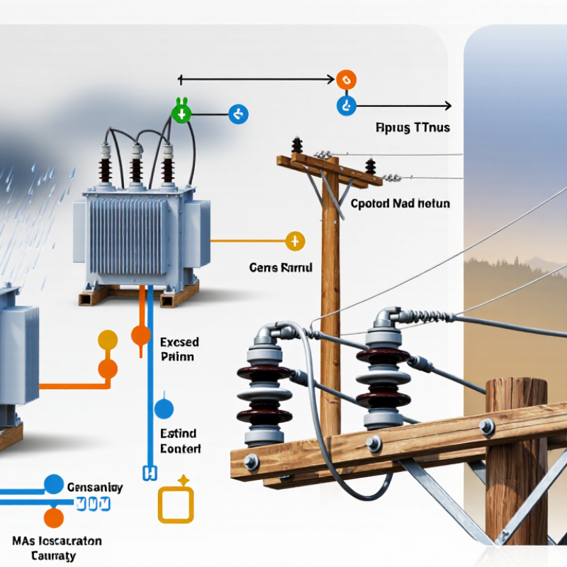
An expulsion fuse protects a circuit by melting a fuse link when current rises beyond its rated limit. The link sits inside an insulating tube, often made with an arc-quenching liner. When the link melts, an electrical arc forms. Heat from the arc releases gases from the liner, pushing the arc outward and helping extinguish it. The circuit opens. It can be noisy.
One easy-to-miss detail is that the fuse’s operation depends on more than its current rating. Its voltage rating, interrupting capacity, time-current characteristics, and coordination with other protective devices all matter. After operation, some designs leave the fuse tube visibly dropped open, which can help workers identify the affected phase. But appearance alone does not confirm that equipment is safe to approach. Selection and replacement should follow equipment data and be handled by qualified personnel.
Tips: Check the system voltage and available fault current against the fuse ratings. Confirm that the fuse coordinates with upstream and downstream protection. Inspect the holder and tube for damage, corrosion, or heat marks. Never replace a fuse with a higher-rated one just to stop repeated interruptions; investigate the cause instead.

Begin with the system’s actual operating voltage, not a guess based on nearby equipment. Check the nameplate, one-line diagram, and utility records. Confirm the system’s maximum voltage, phase configuration, and grounding method. An expulsion fuse’s voltage rating must suit the application; a mismatch can compromise safe interruption. Also verify its interrupting rating against the available fault current at the installation point. Field records are not always tidy. An old drawing may miss a transformer change. Pause and confirm.
Then define the load the fuse must carry. For a transformer, use its kVA rating and primary voltage to estimate full-load current, and check expected operating conditions. The fuse link must carry normal load without nuisance operation, yet respond appropriately to faults. Transformer energization can create brief inrush current, so steady-state current alone is not enough. Review the fuse time-current curve alongside transformer damage limits and upstream and downstream protection. These details are easy to overlook. Actual load patterns may differ from the design sheet, especially where demand changes by season. When voltage, fault-current, or load data are uncertain, have a qualified power-system professional verify them before selecting a fuse.
Expulsion fuse selection starts with the system voltage, not the fuse-link number. IEEE Std C37.42-2016 identifies distribution cutout classes including 15.5, 27, and 38 kV. Match the cutout’s rated voltage and insulation level to the actual system, including its grounding arrangement. A 27 kV label alone does not confirm suitability for every installation.
Then size the link for expected load, transformer inrush, and credible fault current. Its time-current curve should coordinate with downstream protection while allowing normal temporary surges. The cutout’s interrupting rating must exceed available fault current at the installation point. IEEE Std C37.41-2016 sets test requirements for high-voltage fuses and accessories; use equipment data and a fault study, not guesswork. Small details matter. A fuse-link ampere rating is not the same as the cutout’s continuous-current rating.
Check the cutout’s approved link type, tube length, mounting, and operating mechanism. Confirm these against the cutout’s nameplate and technical documentation; similar-looking parts may not fit or perform correctly. I still recheck the coordination curves after a load change. It takes time, but field assumptions can age faster than the hardware.
These examples pair common nominal system voltages with typical cutout voltage classes: 12.47 kV with 15.5 kV, 24.9 kV with 27 kV, and 34.5 kV with 38 kV. Confirm the equipment’s maximum system voltage, insulation level, interrupting rating, and fuse-link coordination against applicable standards and utility requirements before selecting a fuse.
Choosing an expulsion fuse starts with the protection sequence, not just its ampere rating. Compare its minimum-melting and total-clearing curves with downstream devices and upstream relays across the full fault-current range. The downstream fuse should clear a local fault before an upstream device operates, while the upstream protection must still back it up. Check both ends of the curve. A coordination gap at high fault current can be easy to miss.
Use the actual load, transformer inrush, cold-load pickup, and available fault current at the installation point. For example, a fuse that tolerates normal transformer energization may still clear too slowly for a low-level fault. IEEE Std C37.41-2016 provides test requirements for high-voltage fuses; use the relevant manufacturer time-current curves alongside those requirements. IEEE Std 1366-2022 uses five minutes as the threshold for a sustained interruption in reliability indices. That metric describes service continuity, not a safe fuse-clearing time. Verify clearing time against equipment withstand limits and the system’s coordination study. Real networks are rarely tidy, and field settings may differ from the study assumptions.
How to Choose the Right Expulsion Fuses?
Assess Installation Conditions and Maintenance Requirements
Start with the actual installation, not just the circuit’s nominal voltage. Check maximum system voltage, available fault current, load current, and coordination with upstream and downstream protection. The fuse’s interrupting rating must cover the fault current at its location. Then assess exposure: salt spray, dust, altitude, vibration, and strong winds can affect insulation and mechanical operation. A shaded pole beside a road may still collect conductive grime.
EIA’s 2022 Form EIA-861 reliability data report an average of 5.6 hours of electricity interruptions per U.S. customer, including major events. This is system-wide data, not evidence about fuse performance specifically. It does underline why dependable protection and practical inspection access matter. Set maintenance intervals using the applicable utility procedures, equipment instructions, and site conditions. Look for cracked insulators, corrosion, loose connections, damaged fuse tubes, and signs of overheating. A fuse can look clean and still have a poor contact.
Tips: Photograph the installed cutout and record fuse-link ratings before replacement. Confirm the replacement matches the approved coordination study. Never assume a higher amp rating is a safe upgrade. Keep inspection records; small changes are easy to miss.
| Selection Dimension | What to Assess | How It Affects Fuse Selection | Installation and Maintenance Considerations |
|---|---|---|---|
| System voltage and insulation level | Nominal and maximum system voltage, grounding arrangement, and the equipment’s specified insulation level. | Select a fuse cutout rated for the system voltage and insulation requirements. Confirm compatibility with the protected transformer or line. | Check nameplate information and approved equipment documentation before installation. Inspect insulators for cracks, contamination, or tracking. |
| Continuous load current | Expected normal load, permissible overloads, transformer inrush current, and anticipated future load growth. | Choose a fuse link with a continuous-current capability and time-current characteristic appropriate for the load. Avoid selecting solely from transformer kVA without checking application details. | Record operating load and investigate repeated operations. Replace a link only after identifying the cause of an operation and verifying the correct link type and rating. |
| Available fault current | Maximum prospective fault current at the installation point and the system’s voltage conditions. | The cutout’s interrupting capability must be adequate for the available fault current. Coordinate the fuse link’s clearing characteristics with upstream and downstream protection. | Use current system fault-study data where available. Do not install a cutout or link with an interrupting capability below the application requirement. |
| Protection coordination | Transformer damage limits, downstream protective devices, upstream relays or fuses, and the required operating sequence. | Review time-current curves and manufacturer application data so the fuse can protect the equipment while coordinating with other protective devices. | Reassess coordination after system changes, such as transformer replacement, network reconfiguration, or changes in upstream protection. |
| Ambient temperature and solar exposure | Typical and extreme temperatures, direct sunlight, enclosure effects, and local thermal conditions. | Verify that the selected equipment and fuse link are suitable for the expected service conditions; temperature can affect current-carrying performance. | Follow the equipment’s temperature and loading guidance. During inspections, look for discoloration, damaged contacts, or signs of overheating. |
| Altitude | Installation elevation and any altitude limits stated for the cutout. | At higher elevations, reduced air density can affect external insulation and cooling. Confirm whether the equipment requires an altitude-related rating adjustment. | Check the applicable equipment documentation for altitude limitations and any required derating or increased insulation level. |
| Pollution, salt, and moisture | Coastal salt, industrial deposits, dust, agricultural contamination, humidity, and frequency of wetting. | Choose insulation and installation arrangements suitable for the site’s contamination severity and environmental exposure. | Set inspection and cleaning intervals based on site conditions. Use approved cleaning methods and inspect for corrosion, surface damage, and leakage paths. |
| Wind, ice, and mechanical loading | Local wind and ice exposure, vibration, conductor forces, and the strength of the supporting structure. | Confirm that the cutout, mounting hardware, and support can withstand expected mechanical loads and maintain required clearances. | Inspect brackets, fasteners, hinges, and connections for looseness, corrosion, deformation, or movement after severe weather. |
| Mounting position and clearances | Orientation, phase spacing, grounding, conductor routing, and required electrical clearances. | Use a cutout configuration approved for the mounting arrangement. Poor positioning can interfere with operation or compromise clearances. | Installation and adjustment should be performed by qualified personnel using approved drawings and safe work procedures. Verify alignment and secure connections. |
| Access and switching requirements | Whether the location can be reached safely for inspection, fuse-link replacement, and operation with approved tools. | Select an arrangement that suits the site’s operating practices and provides safe access without obstructing nearby equipment. | Maintain safe working clearances and access routes. Follow applicable isolation, grounding, and arc-flash procedures; do not operate damaged equipment. |
| Inspection and replacement planning | Inspection frequency, site criticality, spare-link availability, and the organization’s maintenance procedures. | Prefer an arrangement for which the correct fuse links and compatible components can be identified and managed reliably. | Keep records of fuse operations, inspections, and replacements. Check contacts, terminals, insulators, and the fuse holder; replace damaged or worn parts with approved components. |
Precision Cable Assemblies
16830 Pheasant Drive
Brookfield, WI 53005
Phone: 262-784-7887
Fax: 262-784-0681